Potentiometer principle Potentiometer constructional Basic principles of potentiometers/variable resistors potentiometer experiment circuit diagram
Potentiometer Schematic
Potentiometer schematic Solved calculate how the output voltage range would change The working of a potentiometer
Potentiometer circuit pot diagram working construction method rheostat definition
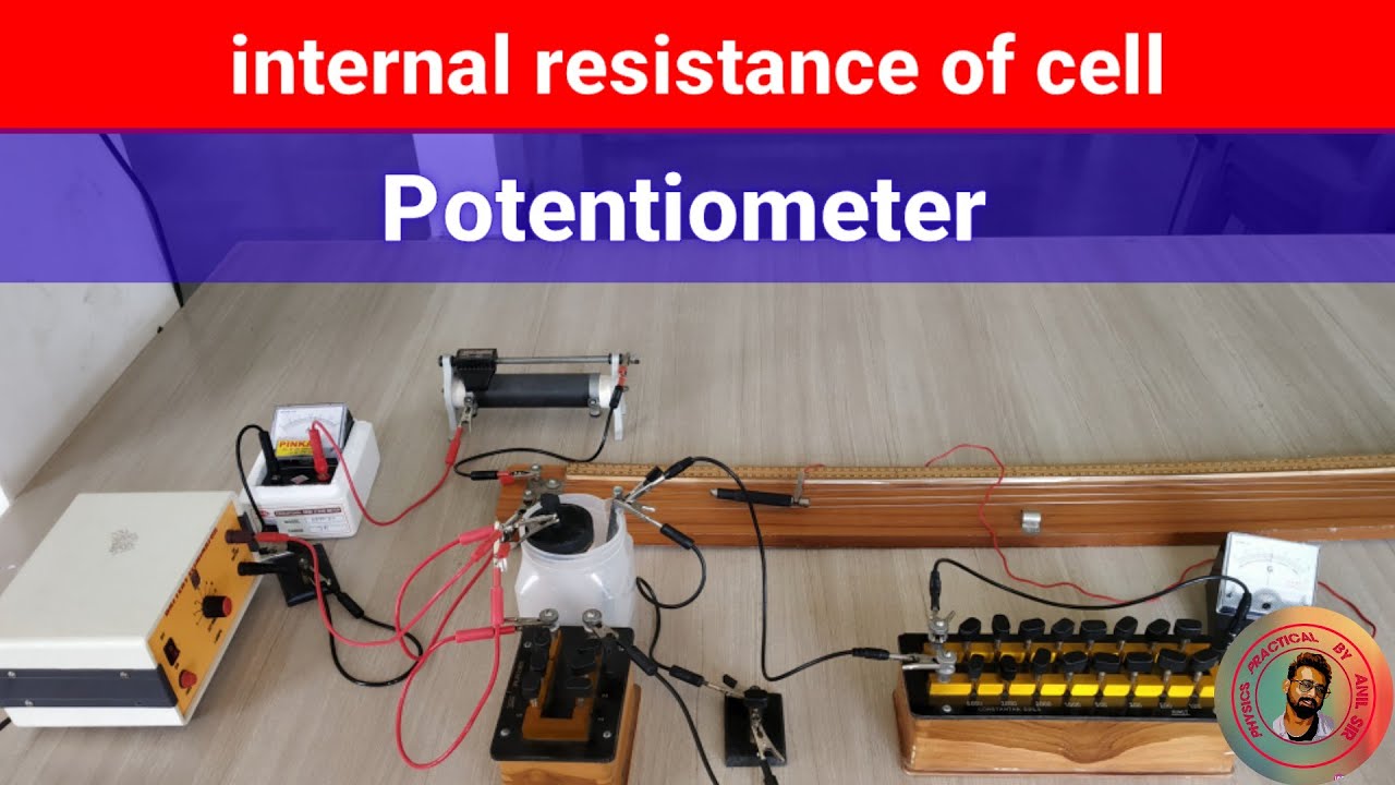
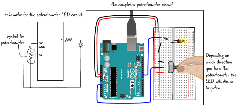
Potentiometers potentiometer arduino 10kωPotentiometer resistance internal experiment cell using Internal resistance of cell using potentiometer || physics practicalResistance potentiometer practical physics.
Potentiometer resistance experiment physics emfs apparatusPotentiometer experiment circuit diagram [proper] potentiometer connection and circuit diagramVoltage potentiometer calculate range circuit divider resistance schematic load change variable output would parallel questions significance explain effect loading source.
Parallel resistor with potentiometer
13+ potentiometer connection diagramPotentiometer emf experiment cell two compare Potentiometer circuit diagramPotentiometer schematic potentiometers variable resistors figure principles basic r4 components passive doeeet connection.
Potentiometer working principle of potentiometerPotentiometer diagram, symbol, and construction Potentiometer schematicPotentiometer resistor variable potensio slide potensiometer tegangan potentiometers menurunkan parallel circuitstoday r1.

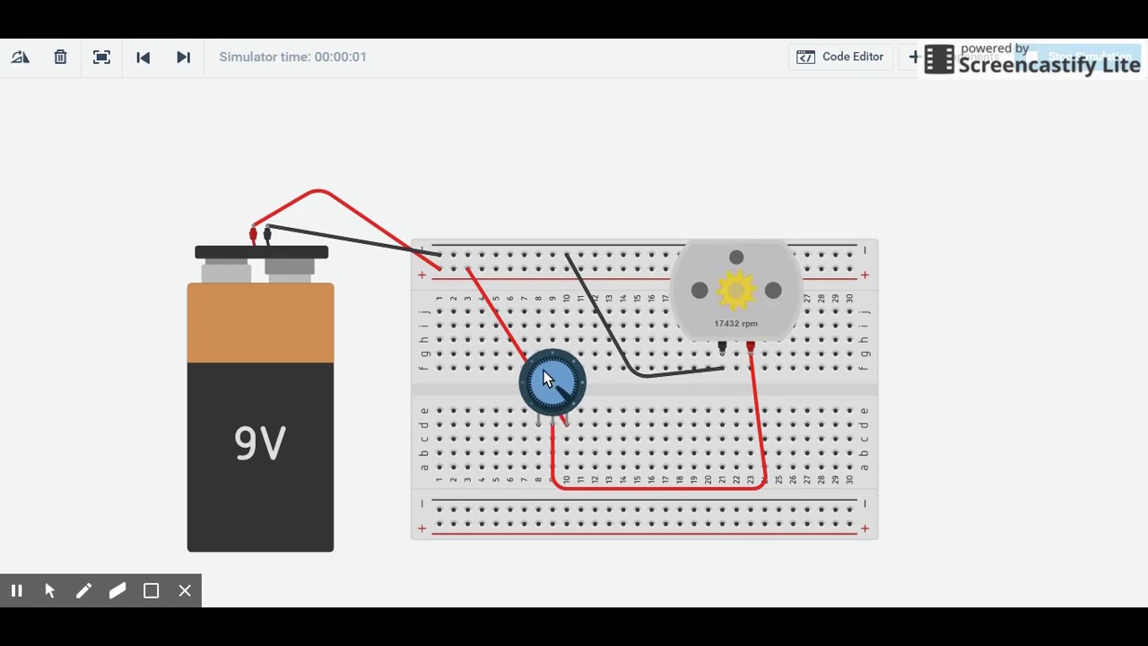
Potentiometer circuit diagram
In a potentiometer experiment the following circuit arrangement is usedExperiment using a potentiometer Potentiometer experiment using physics remove slider plugs separate connection each them two other but do notL4: potentiometers.
Solved © figure 8 shows the potentiometer circuit diagramPotentiometer experiment(internal resistance of a cell using Principles potentiometers potentiometer basic diagram wiring components linearTo compare the emfs of two given primary cells using a potentiometer.

Potentiometer connection
Basics of potentiometers with arduinoPotentiometer diagram wiring What is potentiometer (pot)?Potentiometer experiment (compare emf's of two cell )by anshu kapoor.
.