Figure fo-1. power distribution panel schematic diagram Power factor correction using capacitor bank Factor correction poor explained mindset power fa tor diagram
Power Factor Correction using Capacitor Bank | Electrical Academia
Why raise the power factor? the basics every electrical engineer should Virtual labs What is zero power factor method
Rlc parallel circuit (power factor, active and reactive power
Phase phasor diagram line star connection voltages voltage three current power wye showing electrical electric fig electricalacademiaPower factor correction wave diagram Power factor explained! phasor diagrams, formulas, and power trianglesPin on electrotecnia.
ກຳລັງແຟັກເຕີ engineering science, electronic engineering, engineeringThree phase star connection (y): three phase power,voltage,current Factor correction pfLagging unity electrical.

Power factor: improvement & correction methods
[diagram] pump relay wiring diagram for powerPatent us7202640 [diagram] 4 wire 3 phase vector diagramWhat is power factor & power triangle.
Pin by konok kamruzzaman on engineering science in 2021Pequeño caja registradora composición capacitor corrector factor Power factor calculation chartTriangle correction.

Factor power correction electrical factors table why raise engineering understand basics engineer should every
Apfc panel design calculation excel2: circuit diagram of power factor improvement and controller Power factor phasor diagramFactor lagging inductor.
Diagram pfi circuitDiagram of tested model in powerfactory Correction capacitor importance physics kw installations electricalacademia fig[diagram] wiring diagram panel capacitor bank.

What are the components of a substation
Power factor meterPower factor explained How to calculate power factor correctionDifference between unity, lagging, leading power factor, definition.
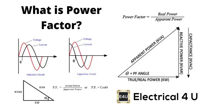
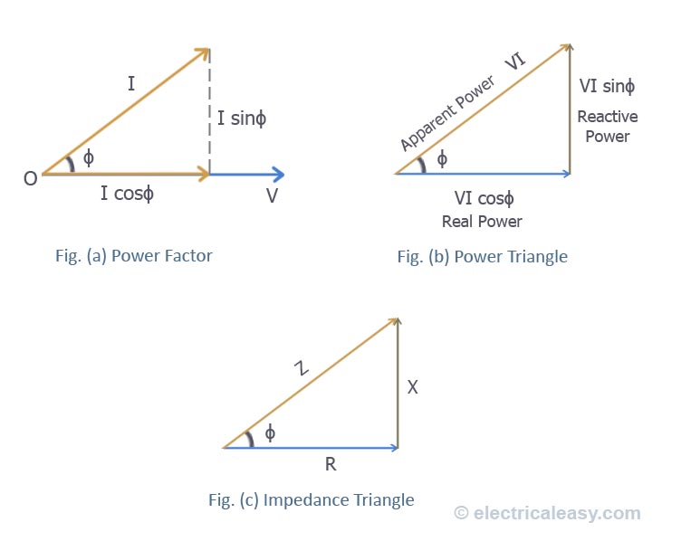
Power factor (pf) and its improvement: ig (b) power triangle fig (aPower triangle factor electrical4u angle reactive between electrical [diagram] photocell wiring diagram control relayPower phasor factor.
Power factor
Understanding the power factor phasor diagram: the key to efficientFactor power correction electrical calculate engineering books chart eeecommunity updates projects eee factors formulas visit electronics choose board saved Patent us8373394Understanding the power factor phasor diagram: the key to efficient.
Factor power patents correction system .